
Using a RaspiRobot Board to Drive a Bipolar Stepper Motor
Problem
You want to control a bipolar stepper motor using a RaspiRobot board.
Solution
The RaspiRobot board uses the same L293D dual H-Bridge chip that you used in “Using a Bipolar Stepper Motor”.
The RaspiRobot board uses the power supply directly from its DC socket as the supply to the motor and regulates that same supply down to 5V to drive the Raspberry Pi. So in this case, the 12V power will be supplying both the 12V stepper motor and the Raspberry Pi.
The Raspberry Pi should not be powered through its USB connection when the RaspiRobot board is also powered, or slight differences in the 5V from the Raspberry Pi USB and the 5V regulated supply from the RaspiRobot board could cause large currents to flow and damage either the board or the Raspberry Pi. Power one board or the other, but not both.
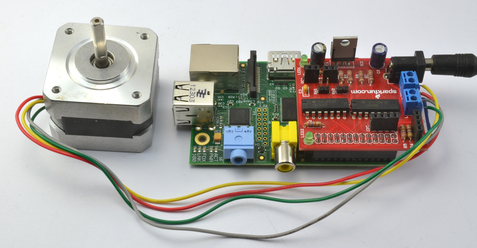
Connect the stepper motor and power supply to the RaspiRobot board as shown in Figure 6-1. The wire colors for the Adafruit 12V stepper motor are in order, from nearest the DC socket: yellow, red, grey, and green.
With a little modification to the pin allocations and step sequence, we can use the program from “Using a Bipolar Stepper Motor” with a RaspiRobot board.
Open an editor (nano or IDLE) and paste in the following code. As with all the program examples in this book, you can also download the program from the Code section of the Raspberry Pi Cookbook website, where it is called stepper_rrb.py. This program uses the command line, so you can run it from SSH.
If you’re using Python 3, change the command raw_input to just input:
importRPi.GPIOasGPIOimporttimeGPIO.setmode(GPIO.BCM)coil_A_1_pin=17coil_A_2_pin=4coil_B_1_pin=10coil_B_2_pin=25GPIO.setup(coil_A_1_pin,GPIO.OUT)GPIO.setup(coil_A_2_pin,GPIO.OUT)GPIO.setup(coil_B_1_pin,GPIO.OUT)GPIO.setup(coil_B_2_pin,GPIO.OUT)forward_seq=['1011','1111','1110','1010']reverse_seq=list(forward_seq)# to copy the listreverse_seq.reverse()defforward(delay,steps):foriinrange(steps):forstepinforward_seq:set_step(step)time.sleep(delay)defbackwards(delay,steps):foriinrange(steps):forstepinreverse_seq:set_step(step)time.sleep(delay)defset_step(step):GPIO.output(coil_A_1_pin,step[0]=='1')GPIO.output(coil_A_2_pin,step[1]=='1')GPIO.output(coil_B_1_pin,step[2]=='1')GPIO.output(coil_B_2_pin,step[3]=='1')whileTrue:set_step('0000')delay=raw_input("Delay between steps (milliseconds)?")steps=raw_input("How many steps forward? ")forward(int(delay)/1000.0,int(steps))set_step('0000')steps=raw_input("How many steps backwards? ")backwards(int(delay)/1000.0,int(steps))
Discussion
The RaspiRobot board uses the L293D in a different arrangement from how you used it in “Controlling the Direction of a DC Motor”, as it uses a pin to enable each channel (pins 17 and 10), and a second pair of pins that controls the direction of each motor (pins 4 and 25). This means that as well as changing the pin allocations, you also need to modify the step sequence to:
forward_seq=['1011','1111','1110','1010']
The first and third bit of each part of the sequence are always 1, enabling both motors. It is now only the second and fourth bits that control the polarity of each of the two stepper windings.
See Also
You can find out more about the RaspiRobot board and other projects that use it at the RaspiRobot website.
To drive a stepper motor using a L293D on a breadboard, see “Using a Bipolar Stepper Motor”.
