
Finding Your Way Around the GPIO Connector
Problem
You need to connect electronics to the GPIO connector, but you need to know more about what all the pins do.
Solution
Figure 2-1 shows the GPIO pinout for both revisions 1 and 2 of the Raspberry Pi Model B. The quick way to tell the boards apart is that if you have an older revision 1 board, it has a black audio socket. The revision 2 boards have a blue audio socket.
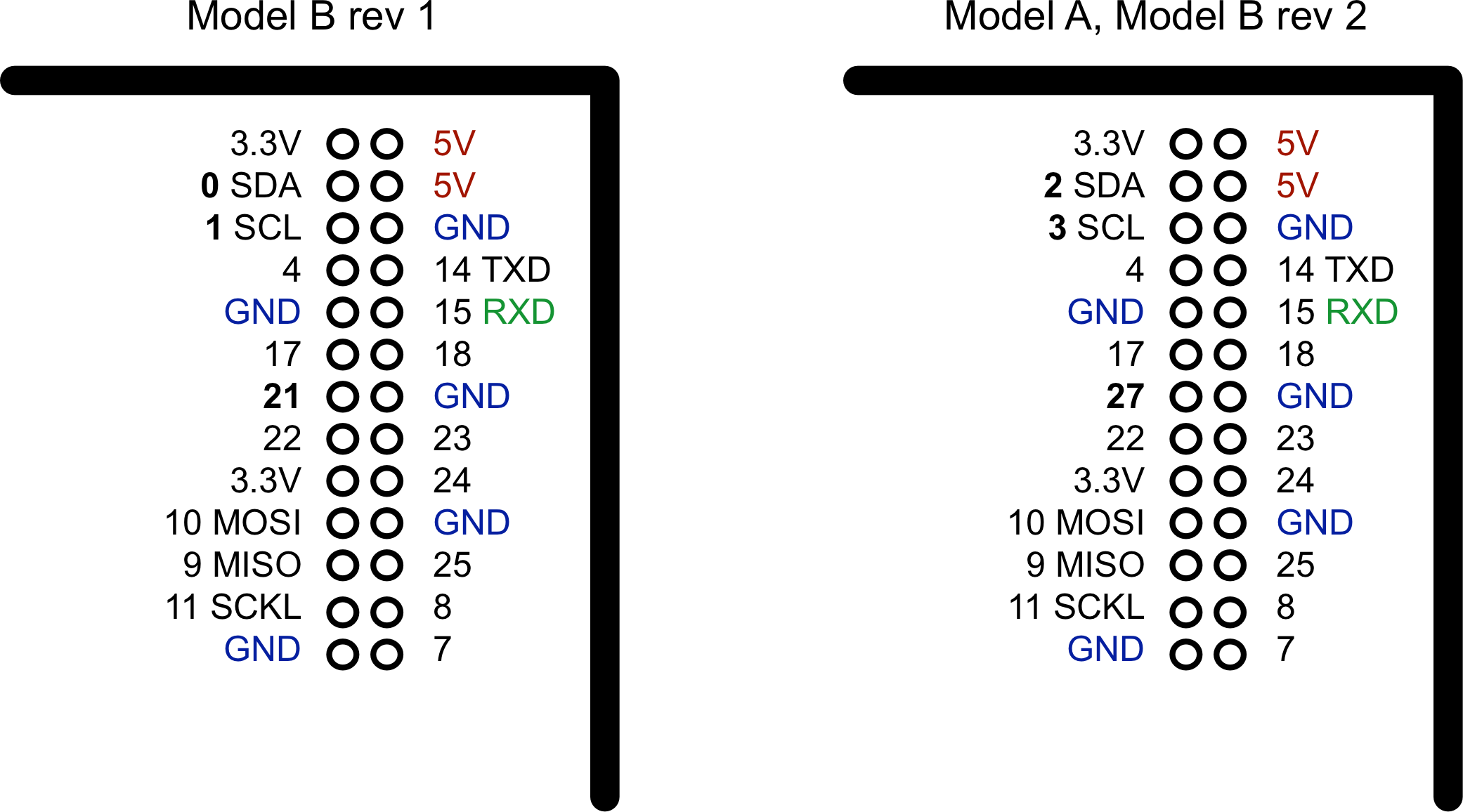
There were three changes to the GPIO connector between revision 1 and revision 2. These are highlighted in bold in Figure 2-1. First, the I2C port was swapped. The two pins SDA and SCL are still SDA and SCL but use a different internal I2C interface. This means that if you’re using the pins as GPIO rather than I2C, then you will refer to them as 2 and 3 on a revision 2 board. Also, GPIO 21 was replaced by GPIO 27 on revision 2.
At the top of the connector, there are 3.3V and 5V power supplies. The GPIO uses 3.3V for all inputs and outputs. Any pin with a number next to it can act as a GPIO pin. Those that have another name after them also have some other special purpose, so 14 TXD and 15 RXD are the transmit and receive pins of the serial interface. SDA and SCL form the I2C interface, and MOSI, MISO, and SCKL from the SPI interface.
Discussion
A GPIO pin can be used as either a digital input or a digital output, and both operate at 3.3V. Unlike the Arduino, the Raspberry Pi does not have any analog inputs. For that you must use an external analog-to-digital converter (ADC) or connect the Pi to an interface board (like the Gertboard) or to an Arduino or an aLaMode board, as discussed in Chapter 14.
See Also
See “Measuring a Voltage” for connecting an ADC to a Raspberry Pi.
